UPVC SWR Pipe Fitting AutoCAD DWG Layout with 2D Connection Plan
Description
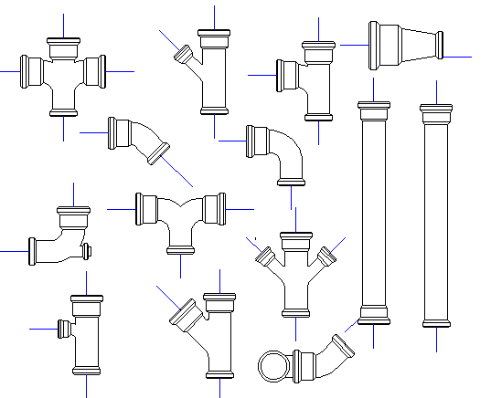
This UPVC SWR Pipes CAD drawing file presents a comprehensive 2D layout showcasing the complete piping network, joint connections, and fitting arrangements. The drawing includes detailed measurements of pipe diameters, flow directions, and alignment paths essential for plumbing, drainage, and sanitary systems. Each element in the AutoCAD DWG file is precisely drawn to ensure accurate planning for civil engineers, MEP designers, and architects. The file covers layout specifications for vertical stacks, inspection chambers, and outlet points, making it an ideal reference for project documentation and installation execution.
Professionals using software such as AutoCAD, Revit, or 3ds Max can utilize this DWG file for infrastructure, building design, and drainage planning projects. The UPVC SWR pipe layout also demonstrates slope angles and connection symbols, ensuring smooth fluid discharge design. This CAD drawing serves as a valuable resource for engineers seeking ready-to-edit plumbing drawings with technical accuracy. Subscribe to Cadbull.com to access and download this professional UPVC SWR pipe AutoCAD layout.
File Type:
DWG
File Size:
3.5 MB
Category::
Dwg Cad Blocks
Sub Category::
Autocad Plumbing Fixture Blocks
type:
Free

Uploaded by:
john
kelly
