Boundary Wall Plan DWG with Structural Details and Dimensions
Description
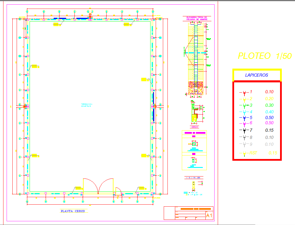
This Boundary Wall Plan DWG provides a complete structural layout designed for accurate construction documentation. The drawing includes full perimeter measurements, detailed wall offsets, column spacing, footing sizes, and reinforcement specifications. Each structural component is marked with precise dimensions, including elevation notes, wall thickness indicators, and typical column section references. The file also includes a plotted pen weight guide, helping architects and engineers understand line hierarchy for printing at 1 to 50 scale. All drawings follow professional drafting standards suitable for AutoCAD, ensuring high clarity for construction teams and project coordinators.
Additionally, the DWG file presents detailed component views such as column reinforcement elevation, foundation layout, cross sections, and support plate locations. Measurements for each segment are clearly represented, supporting accurate site marking and structural verification. This drawing is ideal for architects, civil engineers, and builders who require high precision in boundary wall planning. The included structural annotations and dimension layers help streamline the creation of working drawings. This detailed DWG file enhances project accuracy and offers strong value for users purchasing a Cadbull subscription.

Uploaded by:
Liam
White
